Guide · 5 min read
OTDR pass/fail limits and loss budget
OTDR pass/fail limits are the highest values you accept for each kind of event and for the fibre itself. A common starting point for single-mode fibre is 0.10 dB per fusion splice, 0.50 dB per connector, −35 dB reflectance, and 0.40 dB/km at 1310 nm or 0.30 dB/km at 1550 nm. These are the defaults in OTDR Wizard; your project specification or customer may ask for different values, and you can change every one.
The default limits and why
| Limit | Default | Where it comes from |
|---|---|---|
| Splice loss (non-reflective events) | 0.10 dB | A good fusion splice is usually 0.02–0.05 dB, so 0.10 dB flags splices worth redoing. TIA-568.3-D allows up to 0.3 dB, which many operators find too loose for new builds. |
| Connector loss (reflective events) | 0.50 dB | Typical for a clean, good-quality mated pair. TIA-568.3-D allows 0.75 dB. |
| Reflectance | −35 dB | The usual maximum for single-mode connectors. Values closer to zero (for example −28 dB) mean more light is reflected, which points to a dirty, damaged or badly mated connector. |
| Attenuation at 1310 nm | 0.40 dB/km | Typical maximum for G.652 single-mode fibre in cable. |
| Attenuation at 1550 nm and up | 0.30 dB/km | The same at 1550 nm; also used for 1625 and 1650 nm. |
| Max. total cumulative loss | Off | Your link loss budget. It depends on the link, so there is no default. |
Check your contract or design documents first. Fibre-to-the-home networks, long-haul links and data centres often use different values, and some specifications are stricter at 1550 nm because that wavelength shows bends more clearly.
How each limit is checked
- Splice and connector loss are checked per event. An event is a connector if the OTDR marked it as reflective, and a splice otherwise (see event types). Gainers, events with a negative loss, are not failed: a gain is a measurement effect, not a good splice, and needs a test from the other end to judge.
- Reflectance is checked for every event except the fibre end. Higher means worse: −30 dB fails a −35 dB limit, −45 dB passes.
- Attenuation is checked per fibre section, against the limit for the trace’s wavelength. Sections shorter than 500 m are not judged, because over a short distance the slope is dominated by the nearby events and noise.
- Max. total cumulative loss is checked once per trace, against the cumulative loss at the fibre end.
A failed value is shown in red in the event table, the event’s row is marked, and the reason is written out, for example Connector loss 0.65 dB is above 0.50 dB. The Status tile counts the failed events.
Change the limits
Select the Status tile, or Edit limits under it, to open the limits sheet.
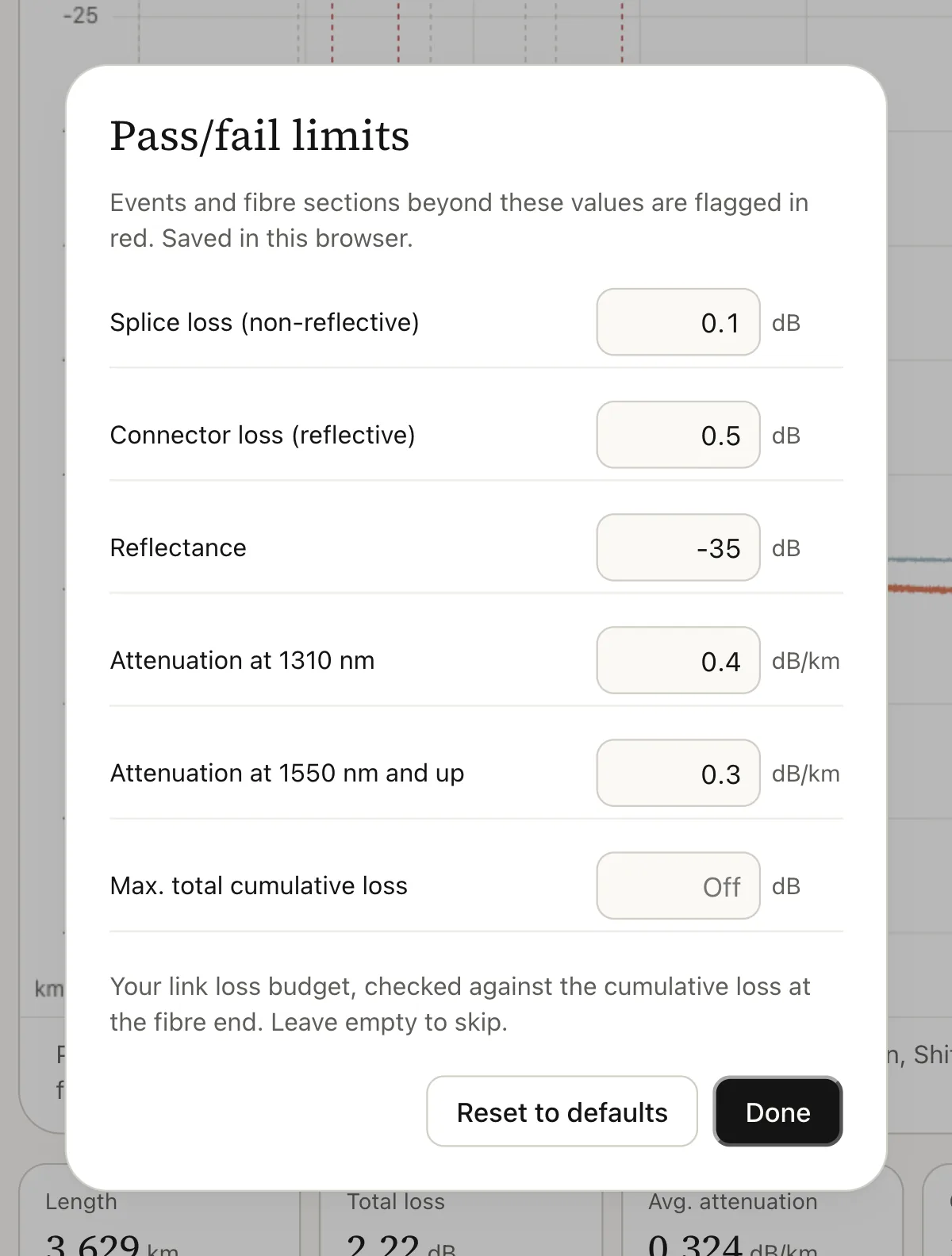
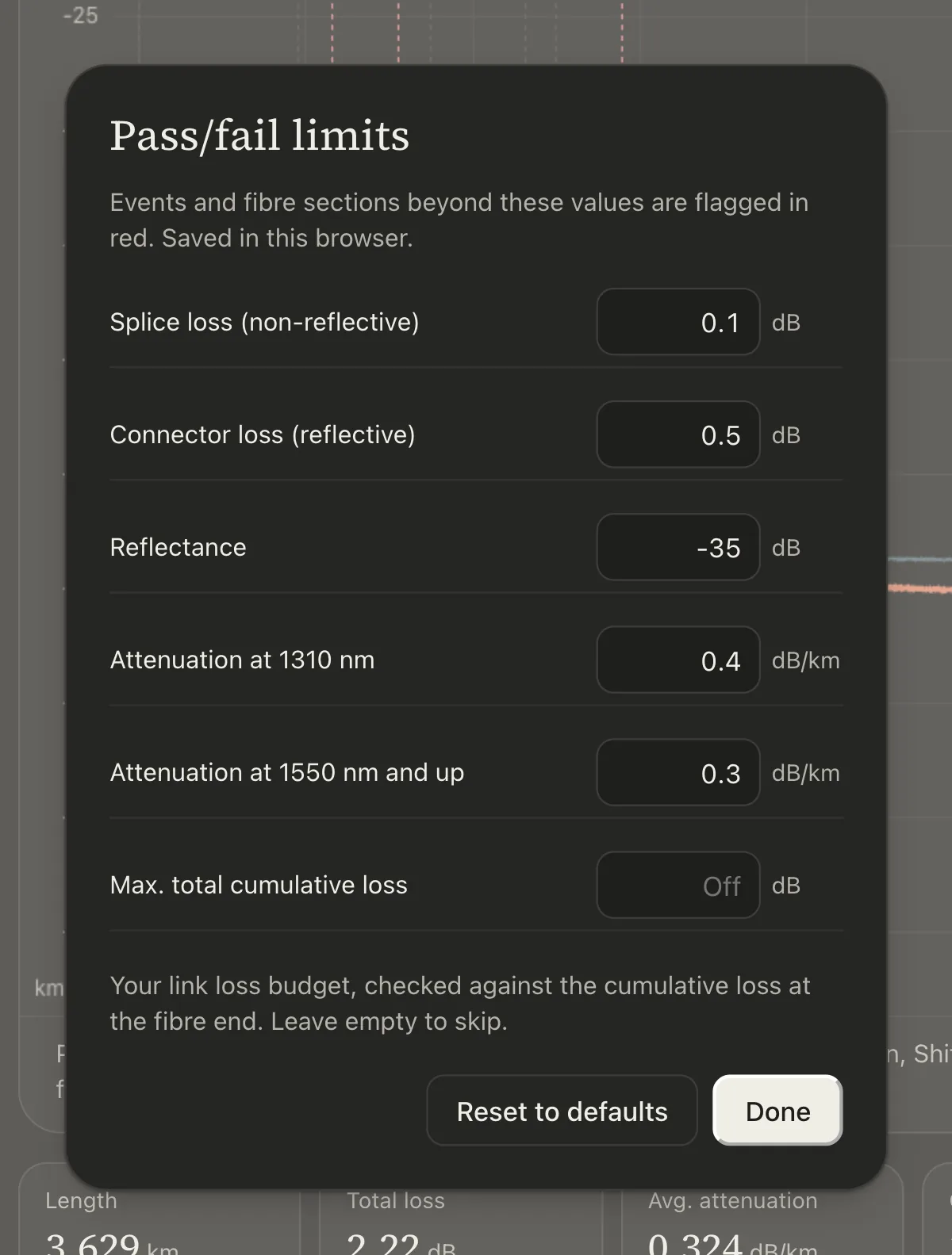
- Splice loss: the maximum loss of a non-reflective event, in dB.
- Connector loss: the maximum loss of a reflective event, in dB.
- Reflectance: the maximum reflectance, in dB. Enter a negative number.
- Attenuation at 1310 nm: in dB/km, used for wavelengths below 1400 nm.
- Attenuation at 1550 nm and up: in dB/km, used for 1400 nm and longer.
- Max. total cumulative loss: your loss budget in dB. Leave it empty to skip this check.
Changes apply at once to every open file. The limits are saved in your browser and used again next time, and they are written into every PDF report and export, so a report always says which limits it was checked against. Reset to defaults restores the values above.
Work out a loss budget
A loss budget is the most loss a link may have and still pass. Add up what the link is made of:
Loss budget = length × fibre attenuation + connectors × connector loss + splices × splice loss
For example, a 12 km link at 1310 nm with 2 connector pairs and 6 splices:
| Part | Calculation | Loss |
|---|---|---|
| Fibre | 12 km × 0.40 dB/km | 4.80 dB |
| Connectors | 2 × 0.50 dB | 1.00 dB |
| Splices | 6 × 0.10 dB | 0.60 dB |
| Loss budget | 6.40 dB |
Enter 6.4 as Max. total cumulative loss. Some designs add a repair margin, often 1 to 3 dB, for future splices; follow your design rules.
The check uses the cumulative loss the viewer calculates from the event table. That figure can differ a little from the total loss the instrument measured end to end; cumulative loss vs total loss explains why and which one to quote.
Check the other direction too
An OTDR measures from one end. A splice between two fibres with different backscatter can look better from one side and worse from the other, and sometimes even shows a gain. For acceptance testing, many specifications ask for traces from both ends, with the splice loss taken as the average of the two readings.